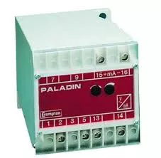
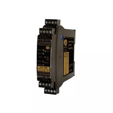
Absolute Process Instruments APD 1520 D _ Bridge, strain gauge, load cell input dual alarm.
Cecomp Electronics, APD 1520 D, Dual Alarm Trip for 1 to 4 Sensor, 9-30 VDC, 10-32 VAC Power
Features with all optional accessories:
- User adjustable setpoint(s)
- User adjustable deadband(s)
- 8 Amp SPDT contacts
- Input LoopTracker LED
- Alarm status LEDs
- Alarm options: LO, HI/HI, LO/LO, band alarm
- Optional reverse acting
- Optional latching alarms
- Push to test/reset
- Remote push to test/reset
- Full I/O/power isolation
- Removable plugs
- DIN rail mount without tools
- Factory Set Input Range and Excitation
- Alarm Test, Optional Reset Button
Applications:
- Load Cell Weighing Systems and Scales
- Strain Gauge Pressure Sensors and Transducers
- Tanks, Scales, Extruder Melt Pressure, Crane Loads
The APD 1520 D accept a strain gauge, bridge, or load cell input and provide a visual alarm indication and alarm relay contact outputs. The input is factory configured to a specific excitation voltage and millivolt input range. The input can be configured as zero-based (i.e., 0 to 20 mV), bipolar (i.e., -30 to +30 mV) for push-pull applications, or offset (i.e., 5 to 33 mV) to electronically compensate for deadweights (tare). The alarm types are factory configured. Front-accessible potentiometers are used to adjust alarm setpoint and deadband.
LoopTracker and Alarm Status LEDs
API exclusive features include a LoopTracker LED that varies in intensity with changes in the process input signal. A two red/green bi-color alarm status LED visually indicate alarm status. These LEDs provide a quick visual picture of your process at all times.
Output Test / Unlatch
API’s exclusive Output Test button can be used to verify the alarm and system operation and also provides the additional function of unlatching the alarm when the latching option has been ordered. This feature can be remotely operated. The output test button greatly aids in saving time during initial startup and/or troubleshooting.
Specifications Table:
| Input | 100 Ω to 10,000 Ω Bridges, 5 mV to 2000 mV, 1-10 VDC Excitation |
| Output | Two 8 Amp SPDT Relays |
| Power to input isolation | 1200 V |
| Common mode protection | 600 VACp or 600 VDC |
| Strain Gauge Input Range | Factory configured, specify sensor mV/V rating and mV range.
|
| Input Impedance | 1 MΩ minimum |
| Excitation Voltage | Factory configured, please specify excitation voltage, Refer to the sensor manufacturer’s recommendations.
|
| Standard Alarm Configuration | 2 setpoints, 2 SPDT relays. HI/LO alarms, non-latching, normal acting |
| Setpoint | 12 turn potentiometer adjustable from 0 to 100% of span |
| Deadband | 12 turn potentiometer adjustable from 1 to 100% of span |
| Response Time | 70 milliseconds typical |
| Ambient Temperature Range and Stability | 10°C to +60°C operating ambient |
| Connectors | Four 4-terminal removable connectors, 14 AWG max wire size |
| Power | 9-30 VDC or 10-32 VAC |